The key to maximizing mechanical seal reliability and minimizing total cost of ownership is in controlling the environment in and around the seal. Du pont de nemours company corporation.

Sigma Seals Products
Mechanical seal configurations and options are as vast as pump models and designs.
. Make sure the seal matches the unit where installation will take place. 511 Make sure that the mechanical seal is corresponding to the assembly drawing. A Place gland with stationary seal face and gasket on the pump shaft.
Refer to page 2 through 6 to identify the seal. Stationary mechanical seal in inch dimensions. The standards put forth by API Standard 682 are meant to give you the tools to optimize product temperaturesmaximize facelubrication minimize leakageandreduceemissions.
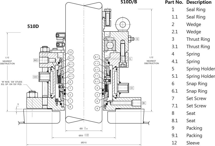
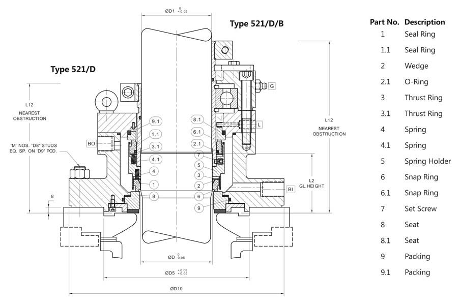
This is known as the primary seal. Drawings of related components may be given on the same sheet. 12 represents an example of a production drawing.
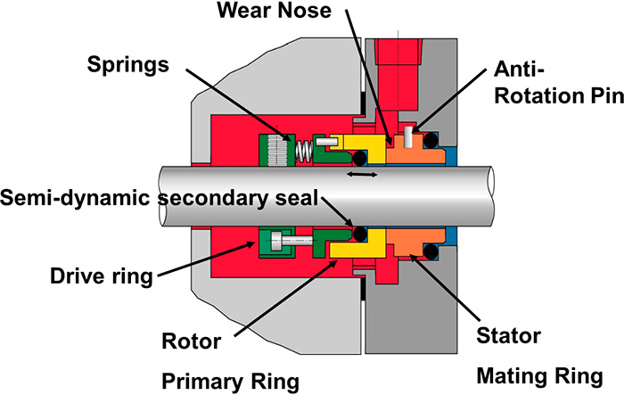
The seal between the rotating 3 and stationary faces 1. In the critical sealing of boiler feed and boiler circulation water Flowserve continues to innovate new technology. Static air pressure test to 100 production.
Probably the most widely recognized and also most common mechanical seal used in general service low pressure applications. Mechanical seals or parts of them which have been subjected to a hit or an impact must be made. 9 Install the mechanical seal in the pump.
Identify the correct replacement seal. B Slide rotary unit on shaft sleeve and set the back of the rotary unit on the second scribe line as determined in step 8. Mechanical seal selection The spring is in the product.
Ø1375 to Ø2625 shaftsleeve gaddis g1 cartridge seal range dwg for ansi pumps big bore. D3 Counterbore or Seat OD. With a lower k value the safety against thermal overload will increase but the mechanical seal may also lift off more easily.
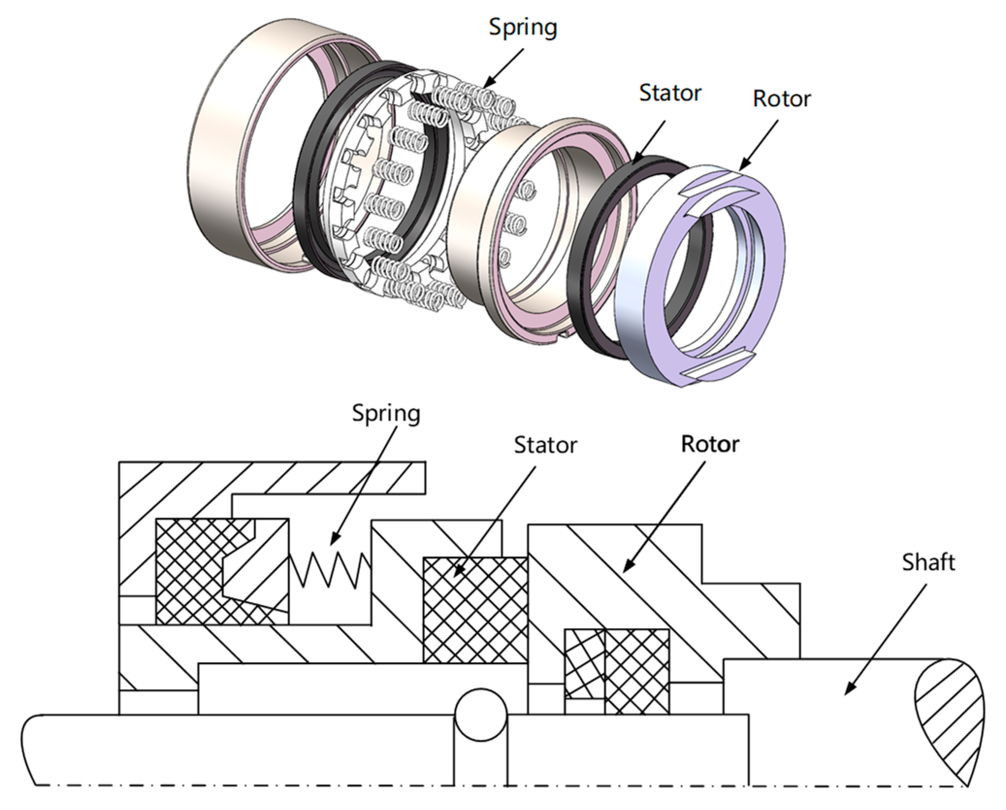
The scope of our mechanical seal product range far exceeds any other seal manufacturer. The seal ring which rotates with the shaft is called the rotary ring. 13There are several types of such drawings.
Rotary O-ring 6. Mechanical seal are the seal rings on which a mechanical force is acting generated by springs or bellows and an hydraulic force generated by the process fluid pressure. From small elastomer bellows seals used in millions of domestic water pumps to double mechanical seals that ensure maximum sealing safety and large highly customized dry-running gas seals for mission critical high speed turbo compressors John Crane has the right product for any.
You can measure according to the Drawing Codes for the correct. In this case two mechanical seals are arranged in series. Fundamental Operating Principle Page 1 of 2.
The seal ring fixed on the casing of the machinery is called the stationary ring. To install a seal the pump would have to be taken off-line and disassembled. TM Mechanical Seals Selecting a replacement Mechanical Seal 861 Cranberry Court Oakville ON L6L 6J7 Phone.
TEMPERATURE-60F TO 400F -50C TO 204C PRESSURE 400 psi 27 bar SPEED 5000 fpm 25 ms 3 T he Liberator II cartridge seal patented offers all of the design features of the Liberator I. A mechanical seal has 4 main sealing points indicated by orange circles as per Figure 3. Mechanical seal and is defined as In practice k values are selected between 065 and 12.
EPDM Neoprene Nitrile Chemraz Kalrez and Viton are available. With this level of local customer focus the Quick Response Centers are ready to respond to. External reservoir pressurized above seal chamber pressure providing barrier fluid to mechanical.
HT L2 Seat Thickness DMR. Sparingly lubricate the pump shaft with John Crane Silicone O-ring. 1625 to 4750 40 mm to 120 mm 15 5 11 12 4 3 2 10 16 1.
Box bore flush connection 4x i wide slots 90 cc. Buffer gas used to dilute seal leakage. Verify that the direction of shaft rotation shown on the seal layout drawing matches the actual rotation of the pump shaft.
The seal between the rotating member and shaft or shaft sleeve 4. If you are unable to identify the seal it will be necessary for you to measure the old seal for correct identification. Packing Although mechanical seals had been around for many decades by 1955 industry had converted only a small percentage of pumps from packing to mechanical seals.
Tures and seal face features to achieve long mechanical seal life. This is due to various reasons. The seal between the stationary member 1 and stuffing box face ie.
123 Assembly drawing A drawing that shows the various parts of a machine in their correct working locations is an assembly drawing as shown in fig. For higher pressures balanced mechanical seals are used. O-RINGS Aflas is standard.
Du pont de nemours company corporation teflon registered trademark e. Basic Mechanical Seals A Mechanical Seals. The product pressure acts additional to the spring on the rotating seal part.
Set screw the rotary unit to the shaft sleeve if seal is supplied with holding clips remove at this time. At Utex we refer to this type as RS-1 The assembly shown in the pump is configured with a. Unlike an O-Ring seal the hydraulic diameter of a bellows seal is not a fixed geometric value.
L1 Seal Head Operation Height OP. Drawing Codes D1 Shaft Size D2 Seal Head OD. SEAL TYPE The mechanical seal shown in the pump photograph is a Type 1 mechanical seal.
The seals are arranged by shaft size from smallest to largest. Installing the Seal 1. Remove the seal drawing from packaging.
Spread throughout the world this type of mechanical seal has reached an unsurpassed quali-ty level. Mechanical Seals For Pumps How Mechanical Seals Work. ROTATING SEAL FACE Alpha sintered Silicon Carbide.
Socket Head Cap Screw 3. Therefore standard mechanical seals are used only for a pressure up to 10 bar. Lower than seal pressure.
To quickly design detailed drawings for parts or seals. 512 Make sure you have all the spare parts to be able to service the machine before proceeding. G-1 single cartridge seals for ansi pumps with big bore stuffing boxes size.
A connect to plan 75 B connect to plan 76 N 2 C A N 2 A Device to be located below pump shaft Used for hot applications or where products have low pressure and are harmfulhazardous. Addressing all the application parameters and fluid behavior characteristics will result in long trouble free mechanical seal service and enhanced pump and process performance. 442Split Mechanical Seal Technical Data 442 SPLIT MECHANICAL SEAL EQUIPMENT BOLT PATTERNS 2 BOLTS 2 BOLTS 3 BOLTS 4 BOLTS All Other Shaft Sizes 2 BOLTS 3 BOLTS 4 BOLTS 4 BOLTS Shaft Sizes.
A118-07-30-01 073018 aflas registered trademark asahi glass company limited viton registered trademark e. It is also influenced by. The BT-A2 features all carbon or high quality resin impregna-ted carbon aluminium oxide 96 is stationary and the rubber bel-lows are glued on collar.

Mechanical Seal An Overview Sciencedirect Topics
Double Seal For Ss Reactor And Double Mechanical Seal For Hydrogenerator Exporter
Back To Basics Mechanical Seals Pumps Systems

Mechanical Seal An Overview Sciencedirect Topics

Component In Mechanical Face Seal 1 Download Scientific Diagram
Energies Free Full Text Multifield Coupling Model And Performance Analysis Of A Hydrostatic Mechanical Seal Html

Pdf Centrifugal Pump Mechanical Seal And Bearing Reliability Optimization Semantic Scholar
Double Seal For Glass Lined Reactor And Double Mechanical Seal For Anfd
0 comments
Post a Comment